
Check 1-1: Switching Inspection
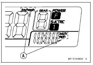
The all LCD segments [A] appear for 3 seconds.
The warning indicator light (Red LED) [B] goes on for 3 seconds and then goes off in a moment after that goes off.
The warning indicator light (Yellow LED) [C] goes on for 3 seconds.
The fuel level (ZX1000J model) or ABS (ZX1000K model) warning indicator light (LED) [D] goes on.
The tachometer (LED) [E] blinks 3 times.
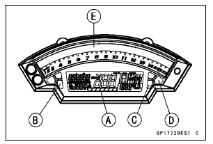
If the meter does not work, replace the meter unit.
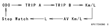
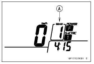
This display is ordinary indication.
If the meter does not work, replace the meter unit.
If meter does not work, replace the meter unit.
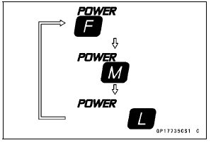
Normal Mode [A] Race Mode [B]
NOTE
Mile/Km Display can alternate between English and metric modes (mile and km) in the digital meter. Make sure that km or mile according to local regulations is correctly displayed before riding.
If the display function does not work, replace the meter unit.
If the indicator symbol does not work, check the following parts.
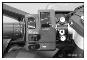
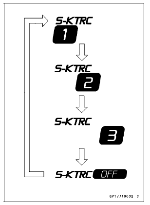
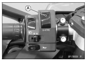
S-KTRC Button (see Switch Inspection) Wiring (see Meter Unit Circuit)
If the above parts is good, replace the meter unit and/or ECU.
If the display function does not work, check the following parts.
Power Mode Button (see Switch Inspection) Wiring (see Meter Unit Circuit)
If the above parts is good, replace the meter unit and/or ECU.
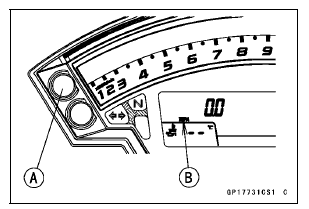
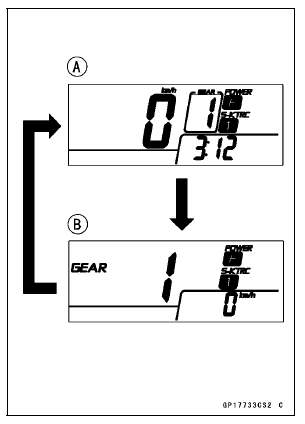
Check 1-2: Gear Position Indication Inspection
The neutral indicator light (LED) [A] goes on when the transmission gear is neutral position.
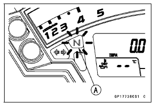
(This illustration shows normal mode.)
If the display function does not work, check the following parts.
Gear Position Switch (see Gear Position Switch Inspection) Wiring (see Meter Unit Circuit)
If the above parts is good, replace the meter unit and/or ECU.
 Meter Unit Removal/Installation
Coolant Filling
Remove the bolts and quick rivets.
Detach the tabs and remove the right
fairing and cover.
A. Bolts
B. Quick Rivet
C. Large Quick Rivet
D. Tabs
E. Right Fairing and Cover
NOTE
The right fairing and cover uses the
quick rivets and large quick rivet.
The large quick rivet ca ...
Oxygen Sensor Heater Resistance Inspection
Turn the ignition switch to OFF.
Remove the fuel tank (see Fuel Tank Removal in the Fuel
System (DFI) chapter).
Disconnect the oxygen sensor lead connector [A].
Connect a digital meter [A] to the terminals in the oxygen
sensor lead connector [B].
Measure the oxygen sensor heat ...
Brakes
Brake Wear Inspection
Inspect the brakes for wear. For each
front and rear disc brake caliper, if the
thickness of either pad is less than
1 mm (0.04 in.), replace both pads
in the caliper as a set. Pad replacement
should be done by an authorized
Kawasaki dealer.
A. Lining Thickness
B. ...
