
Turn Signal Relay [A] Turn Signal Lights [B] 12 V Battery [C]
If the lights do not blink as specified, replace the turn signal relay.
Testing Turn Signal Relay 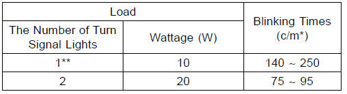
(*): Cycle(s) per minute
(**): Corrected to “one light burned out”.
Turn Signal Light Circuit
1. Ignition Switch
2. Joint Connector A
3. Rear Right Turn Signal Light 12 V 10 W
4. Rear Left Turn Signal Light 12 V 10 W
5. Joint Connector B
6. Battery
7. Main Fuse 30 A
8. Frame Ground
9. Turn Signal Relay
10. Turn Signal Switch
11. Turn Signal Relay Fuse 10 A
12. Fuse Box 1
13. Front Left Turn Signal Light (LED)
14. Front Right Turn Signal Light (LED)
15. Turn Signal Indicator Light (LED)
 Rear Turn Signal Light Bulb Replacement
 Air Switching Valve
Wiring Diagram (Other than US, CA and CAL without KIBS Models)
ZX1000JC
ZX1000JD
...
Braking
Close the throttle completely, leaving
the clutch engaged (except when
shifting gears) so that the engine will
help slow down the motorcycle.
Shift down one gear at a time so that
you are in 1st gear when you come
to a complete stop.
When stopping, always apply both
brakes at the ...
Cylinder Head Cover Removal
Remove:
Air Suction Valves (see Air Suction Valve Removal)
Throttle Body Assy (see Throttle Body Assy Removal in
the Fuel System (DFI) chapter)
Stick Coils (see Stick Coil Removal in the Electrical System
chapter)
Remove the clamps [A].
Turn up the front side of the heat insulation ...