
NOTICE
Do not remove the clutch release lever and shaft assembly unless it is absolutely necessary. If removed, the oil seal replacement may be required.
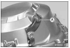
 Clutch Cover Installation
 Release Shaft Installation
Oil Level Inspection
Check that the engine oil level is between the upper [A]
and lower [B] levels in the gauge.
NOTE
Situate the motorcycle so that it is perpendicular to the
ground.
If the motorcycle has just been used, wait several minutes
for all the oil to drain down.
If the oil has just been changed, ...
Air Cleaner Element Replacement
NOTE
In dusty areas, the element should be replaced more
frequently than the recommended interval.
WARNINGIf dirt or dust is allowed to pass through
into the
throttle body assy, the throttle may become stuck,
possibly causing accident. Replace the air cleaner
element according ...
Engine Sprocket Installation
Replace the sprocket washer and axle cotter pin.
Install the engine sprocket onto the output shaft.
Apply molybdenum disulfide oil solution to the threads
and seating surface of the engine sprocket nut.
Tighten:
Torque - Engine Sprocket Nut: 145 N·m (14.8 kgf·m, 107
ft·lb)
NOTE
...