
S-KTRC is an intelligent system that calculates the slip level of the rear wheel (wheelspin) and is suitable for sports riding conditions. S-KTRC is designed to function on public roads.
Acceleration may be delayed under certain circumstances depending on road conditions. S-KTRC cannot respond to every condition.
| WARNING S-KTRC cannot protect the rider from all possible hazards and is not a substitute for safe riding practices. All riders must be aware of how the S-KTRC system operates and its limitations. It is still your responsibility to ride at appropriate speeds and throttle control for weather, road surface and traffic conditions. |
The S-KTRC functions at 5 km/h (3.1 mph) or more, and stops functioning at 4 km/h (2.5 mph) or below.
| WARNING Use of nonrecommended tires could cause a malfunction or improper operation of S-KTRC. Always use recommended standard tires for this motorcycle. |
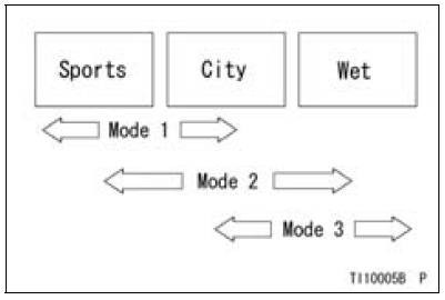
MODES
The S-KTRC determines the traction control characteristics with three mode selections. The S-KTRC can also be set to OFF.
The S-KTRC and the Power mode can be set separately. By combining each setting, the rider can get various riding feelings.
MODE 1:
The S-KTRC least intervenes among the three modes. This makes lengthy drifts and wheelies possible when exiting tight corners.
MODE 2:
There is more S-KTRC intervention compared tomode 1. Thismakes slight drifts possible when exiting tight corners.
MODE 3:
The S-KTRC intervenes early enough to prevent the rear wheel from spinning whenever possible.
[Example]
(Actual ranges vary with rider skills)
S-KTRC Button
Use the S-KTRC button on the left hadle switch to set the S-KTRC mode.
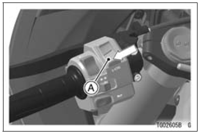
A. S-KTRC Button (Lower Part)
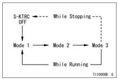
Themode can be changed only when the throttle grip is closed completely.
NOTE
When changing the mode, stop the motorcycle.
 0.4
0.4
NOTE
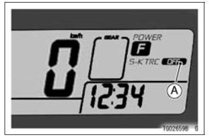
A. S-KTRC OFF Indicator
NOTE
 Catalytic Converter
 Power mode
Storage
Preparation for Storage
Clean the entire vehicle thoroughly
Run the engine for about five minutes to warm the oil, shut it off, and
drain the
engine oil.
WARNINGEngine oil is a toxic substance. Dispose
of used oil properly. Contact
your local authorities for approved disp ...
Check 3-7 Stop Watch Inspection
Connect the leads in the same circuit as Check 3-2.
By pushing the upper button each time to set the stop
watch mode.
Connect the insulated auxiliary lead processed insulation
to the terminal [13] as shown in the figure, then stop watch
start to count.
While count the stop watch, conn ...
Gear Position Switch Inspection
NOTE
Be sure the transmission and external shift mechanism
are good condition.
Remove the fuel tank (see Fuel Tank Removal in the Fuel
System (DFI) chapter).
Disconnect the connector [A].
Set the hand tester [A] to the × 1 kΩ or × 100 Ω range
and connect i ...