
Replace the fuel hose if any fraying, cracks [B] or bulges [C] are noticed.
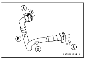
Replace the hose if it has been sharply bent or kinked.
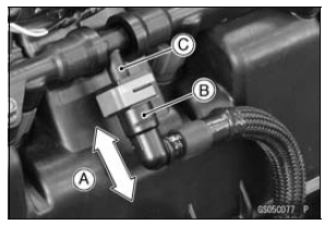
Push and pull [A] the fuel hose joint [B] back and forth more than two times, and make sure it is locked.
Check the other hose joint in the same way.
NOTICE
When pushing and pulling the fuel hose joint, do not apply strong force to the delivery pipe [C] on the nozzle assy. The pipe made from resin could be damaged.
| WARNING Leaking fuel can cause a fire or explosion resulting in serious burns. Make sure the hose joint is installed correctly on the delivery pipe by sliding the joint. |
If it does not locked, reinstall the hose joint.
 Idle Speed Inspection
 Evaporative Emission Control System Inspection (CAL and SEA-B1 Models)
For Secondary Fuel Injectors
Remove the fuel tank (see Fuel Tank Removal).
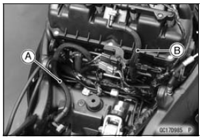
Disconnect the secondary fuel injector connector [A].
Connect a digitalmeter to the terminals in each secondary
fuel injector [A].
Measure the secondary fuel injector resistance.
Secondary Fuel Injector Resistance
Standard: Abo ...
Main Throttle Sensor Resistance Inspection
Turn the ignition switch to OFF.
Measure the main throttle sensor resistance in the same
way as input voltage inspection, note the following.
Disconnect the throttle sensor setting adapter [A] from the
connector of the main harness side.
Special Tool - Throttle Sensor Setting Adapter: 57 ...
Sprocket Wear Inspection
Visually inspect the engine and rear sprocket teeth for
wear and damage.
If the teeth are worn as illustrated, replace the sprocket,
and inspect the drive chain wear (see Drive Chain Wear
Inspection in the Periodic Maintenance chapter).
Worn Tooth (Engine Sprocket) [A]
Worn Tooth (Rear ...