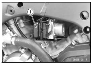

1. KIBS ECU
With input from the front and rear wheel sensors and front caliper hydraulic pressure, the KIBS ECU analyzes various conditions on the motorcycle, and with additional information from the FI ECU (engine speed, throttle position, gear position, and clutch actuation) precisely controls the brake caliper hydraulic pressure. As a result, brake force is generated to suit conditions. If there is no engine information from the FI ECU, the KIBS is deactivated and the warning is displayed in the meter; however, the conventional ABS function is maintained.

2. Wheel Rotation Sensor
The wheel rotation sensor converts the front and rear wheel rotation speed to a pulse signal and transmits it to the KIBS ECU and FI ECU.
3. KIBS Hydraulic Unit
The KIBS hydraulic unit consists of the hydraulic unit and KIBS ECU and has the front caliper hydraulic pressure sensor built-in.
When receiving a signal fromthe KIBS ECU, the hydraulic unit increases or decreases the front and rear brake hydraulic pressure.
The front caliper hydraulic pressure sensor always monitors the front caliper hydraulic pressure and transmits the hydraulic pressure change to the KIBS ECU.
4. FI ECU
The FI ECU transmits information from the crankshaft sensor (engine speed), the main throttle sensor (throttle position), the gear position switch (gear position), and the starter lockout switch (ON/OFF) to the KIBS ECU by the CAN system.
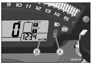
5. Multifunction Meter
When a failure occurs in the system, themultifunction meter displays the warning indication by turning ON the warning indicator light (yellow LED) [A] and KIBS symbol [B].

 Overview
 Related Parts Locations
Radiator and Cooling Fan
Check the radiator fins for obstruction
by insects or mud. Clean off
any obstructions with a stream of
low-pressure water.
WARNINGThe cooling fan spins at high
speed and can cause serious
injuries. Keep your hands and
clothing away from the cooling
fan blades at all times.
...
Water Pump Inspection
Remove the left lower fairing (see Lower Fairing Removal
in the Frame chapter).
Check the drainage outlet passage [A] at the bottom of
the water pump body for coolant leaks.
If the mechanical seal is damaged, the coolant leaks
through the seal and drains through the passage. Replace
th ...
ESD (Electronic Steering Damper) ECU Communication Error (Service Code 3C,
ZX1000JD/KD)
ESD ECU Communication Line Inspection
When the data (for status of ESD system) is not sent from
the ESD ECU to the meter unit and ECU, the service code
3C is displayed.
The data is sent through the CAN communication line.
The service code 3C is detected with the meter unit.
The FI symbol does ...