
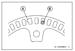
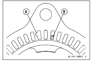
If the rotor is deformed or damaged (chipped teeth [A]), replace the sensor rotor with a new one.
If there is iron or other magnetic deposits [B], remove the deposits.
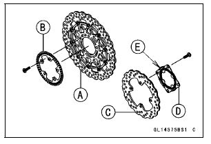
When installing the rear wheel rotation sensor rotor, the bended end [E] faces to disc side.
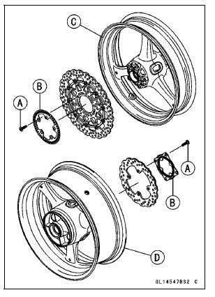
Install the brake discs (see Brake Disc Installation).
KIBS Solenoid Valve Relay Fuse (20 A) Removal
Refer to the Fuse Box Fuse Removal in the Electrical System chapter.
KIBS Motor Relay Fuse (30 A) Removal
Refer to the Fuse Box Fuse Removal in the Electrical System chapter.
Fuse Installation
If a fuse fails during operation, inspect the electrical system to determine the cause, and then replace it with a new fuse of proper amperage (see Fuse Installation in the Electrical System chapter).
Fuse Inspection
 Wheel Rotation Sensor Air Gap Inspection
 Suspension
Cooling System Flushing
Over a period of time, the cooling system accumulates
rust, scale, and lime in the water jacket and radiator. When
this accumulation is suspected or observed, flush the cooling
system. If this accumulation is not removed, it will clog
up the water passage and considerable reduce the efficiency
...
Starting the Engine
Check that the engine stop switch is
in the
position.
A. Engine Stop Switch
B. Starter Button
Turn the ignition key to “ON”.
Make sure the transmission is in neutral.
A. Neutral Indicator Light
B. Ignition Switch
C. “ON” position
NOTE
The motorcycle is equipped w ...
Crankcase Assembly
NOTICE
The upper and lower crankcase halves are machined
at the factory in the assembled state, so the
crankcase halves must be replaced as a set.
With a high flash-point solvent, clean off the mating surfaces
of the crankcase halves and wipe dry
WARNINGGasoline and low flash-poin ...