
Turn Signal Relay [A] Turn Signal Lights [B] 12 V Battery [C]
If the lights do not blink as specified, replace the turn signal relay.
Testing Turn Signal Relay 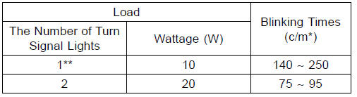
(*): Cycle(s) per minute
(**): Corrected to “one light burned out”.
Turn Signal Light Circuit
1. Ignition Switch
2. Joint Connector A
3. Rear Right Turn Signal Light 12 V 10 W
4. Rear Left Turn Signal Light 12 V 10 W
5. Joint Connector B
6. Battery
7. Main Fuse 30 A
8. Frame Ground
9. Turn Signal Relay
10. Turn Signal Switch
11. Turn Signal Relay Fuse 10 A
12. Fuse Box 1
13. Front Left Turn Signal Light (LED)
14. Front Right Turn Signal Light (LED)
15. Turn Signal Indicator Light (LED)
 Rear Turn Signal Light Bulb Replacement
 Air Switching Valve
Leather, Vinyl, and Rubber
If your motorcycle has leather accessories,
special care must be taken.
Use a leather cleaner/treatment to
clean and care for leather accessories.
Washing leather parts with detergent
and water will damage them, shortening
their life.
Vinyl parts should be washed with the
rest of themo ...
Intake Air Pressure Sensor #1 Removal
NOTICE
Never drop the intake air pressure sensor #1 especially
on a hard surface. Such a shock to the sensor
can damage it.
Remove:
Air Cleaner Housing (see Air Cleaner Housing Removal
in the Fuel System (DFI) chapter)
Intake Air Pressure Sensor #1 Connector [A]
Remove the intake air ...
Front Fork Inspection
Holding the brake lever, pump the
front fork up and down several times
to inspect smooth stroke.
Visually inspect the front fork for oil
leakage, scoring or scratches on the
outer surface of the inner tube.
If any doubt about the front fork, it
should be checked by an authorized
K ...