
NOTICE
The wheel rotation sensor should be handled carefully, never struck sharply, as with a hammer, or allowed to fall on a hard surface since the wheel rotation sensor is precision made. Be careful not to get water or mud on the wheel rotation sensor.
Do not try to disassemble or repair the wheel rotation sensor.
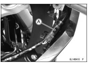
Headlight Mounting Bolt [B]
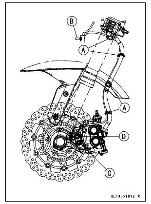
Front Wheel Rotation Sensor Installation
Run the lead correctly (see Cable, Wire, and Hose Routing section in the Appendix chapter).
 KIBS Hydraulic Unit Inspection
 Rear Wheel Rotation Sensor Removal
Subthrottle Valve Actuator Resistance Inspection
Turn the ignition switch to OFF.
Disconnect the subthrottle valve actuator connector [A].
Connect a digital meter to the subthrottle valve actuator
connector [A].
Measure the subthrottle valve actuator resistance.
Subthrottle Valve Actuator Resistance
Connections: Y/BK lead [1 ...
What Am I Responsible For?
You are responsible for maintaining your vehicle according to the maintenance
schedule shown in this owner’s manual.
You are responsible for notifying your dealer immediately if there is a problem,
and you, as the owner, will need to authorize the dealer to inspect the unit.
You will be re ...
Exploded View
25. “1T� marked side faces up.
26. “T2� marked side faces up.
27. Hollow mark faces exhaust side.
G: Apply grease.
L: Apply a non-permanent locking agent.
LG: Apply liquid gasket.
M: Apply molybdenum disulfide grease.
MO: Apply molybdenum disulfide oil solution.
...