

Do not remove the nozzle assy from the air cleaner housing.
Be sure to place a piece of cloth around the fuel outlet pipe of the fuel pump and the delivery pipe of the throttle body assy.
| WARNING Fuel is flammable and explosive under certain conditions and can cause severe burns. Be prepared for fuel spillage; any spilled fuel must be completely wiped up immediately. When the fuel hose is disconnected, fuel spills out from the hose and the pipe because of residual pressure. Cover the hose connection with a piece of clean cloth to prevent fuel spillage. |
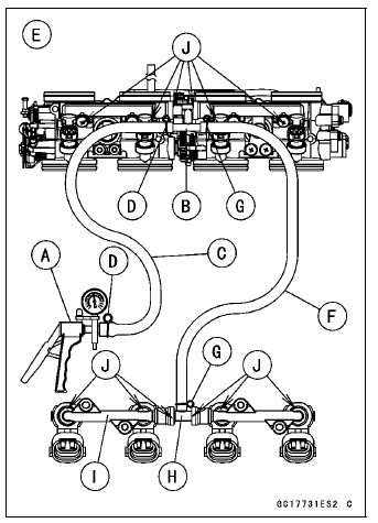
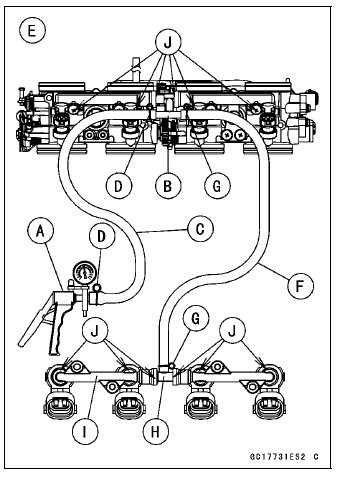
Connect a commercially available vacuum/pressure pump [A] to the nipple of the delivery pipe [B] with the fuel hose [C] (both ends with the clamps [D]) as shown in the figure.
Rear View [E]

Apply soap and water solution to the areas [J] as shown in the figure.
Watching the pressure gauge, squeeze the pump lever, and build up the pressure until the pressure reaches the maximum pressure.
Injector Fuel Line Maximum Pressure Standard: 300 kPa (3.06 kgf/cm², 43 psi)
NOTICE
During pressure testing, do not exceed the maximum pressure for which the system is designed.
Watch the gauge for at least 6 seconds.
If the pressure holds steady, the fuel line is good.
If the pressure drops at once or if bubbles are found in the area, the fuel line is leaking. Replace the delivery pipe assy, injectors and related parts.
Install: Primary and Secondary Fuel Hoses (see Fuel Hose Replacement in the Periodic Maintenance chapter) Air Cleaner Housing (see Air Cleaner Housing Removal) Fuel Tank (see Fuel Tank Removal)
Start the engine and check for fuel leakage.
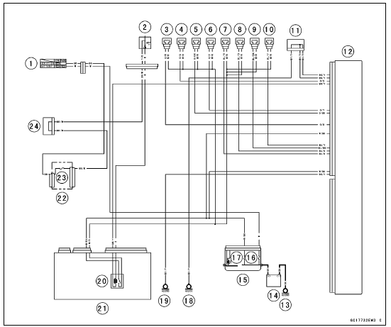
Fuel Injector Circuit

1. Ignition Switch
2. Engine Stop Switch
3. Secondary Fuel Injector #1
4. Secondary Fuel Injector #2
5. Secondary Fuel Injector #3
6. Secondary Fuel Injector #4
7. Primary Fuel Injector #1
8. Primary Fuel Injector #2
9. Primary Fuel Injector #3
10. Primary Fuel Injector #4
11. Joint Connector E
12. ECU
13. Engine Ground
14. Battery
15. Starter Relay
16. Main Fuse 30 A
17. ECU Fuse 15 A
18. Frame Ground 2
19. Frame Ground 1
20. Fuel Pump Relay
21. Relay Box
22. Fuse Box 1
23. Ignition Fuse 15 A
24. Joint Connector F
 Fuel Injector Output Voltage Inspection
 Throttle Grip and Cables
Gear Position Switch Removal
Remove:
Oil Pump (see Oil pump Removal in the Engine Lubrication
System chapter)
Engine Sprocket (see Engine Sprocket Removal in the
Final Drive chapter)
Fuel Tank (see Fuel Tank Removal in the Fuel System
(DFI) chapter)
Disconnect the connector [A].
Remove:
Screws [A]
...
KIBS Servicing Precautions
There are a number of important precautions that should
be followed servicing the KIBS.
This KIBS is designed to be used with a 12 V sealed battery
as its power source. Do not use any other battery
except for a 12 V sealed battery as a power source.
Do not reverse the battery cable connec ...
Diode Circuit Inspection
Remove the relay box (see Relay Box Removal).
Check conductivity of the following pairs of terminals (see
Relay Box Internal Circuit in this section).
Diode Circuit Inspection
The resistance should be low in one direction and more
than 10 times as much in the other direction. If any dio ...