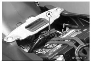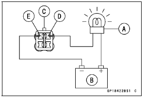


Connections: Battery (+) → 12 V 3.4 W Bulb (One Side) 12 V 3.4 W Bulb (Other Side) → R/BK lead [D] Battery (–) → BK/W lead [E]
If the test light turn on, the reserve switch is defective.
Replace the fuel pump.

Connections: Battery (+) → 12 V 3.4 W Bulb (One Side) 12 V 3.4 W Bulb (Other Side) → R/BK lead Battery (–) → BK/W lead
If the test light does not light, replace the fuel pump.
NOTE
It may take a long time to turn on the test light in case that the fuel reserve switch is inspected just after the fuel is drawn. Leave the fuel pump lead connector with leads for inspection connected for few minutes.
 Water Temperature Sensor Inspection
 Oxygen Sensor Removal (Equipped Models)
Engine No. ZXT00JE003022
1. Heat Insulation Rubber Plate
2. For Air Switching Valve Hoses (Place the air switching valve above the
rubber plate.)
3. For Air Suction Valve Cover
4. For Throttle Body Assy Holder #2 and #3
5. For Throttle Body Assy Holder #1
6. For Water Temperature Sensor
7. Insert the tab into th ...
Parking
WARNINGOperating or parking the vehicle
near flammable materials can
cause a fire, and can result in
property damage or severe personal
injury.
Do not idle or park your vehicle
in an area where tall or dry vegetation,
or other flammable materials
could come into cont ...
DFI System
1. ECU
2. Battery
3. Vehicle-down Sensor
4. Exhaust Butterfly Valve Actuator
5. Vacuum Chamber (Other than US, CA and CAL Models)
6. Air Intake Valve Actuator (Other than US, CA and CAL Models)
7. Air Intake Valve (Other than US, CA and CAL Models)
8. Air Flow
9. Air Intake Solenoid Valve ...