
1. Green Hose (Purge)
2. Clamp (hold the white hose.)
3. Canister
4. White Hose (Vacuum)
5. Blue Hose (Breather)
6. Red Hose (Return)
7. Separator
8. Quick Rivet
9. Face the hook portion of the bracket to inside of the vehicle.
10. Clamp (Bend down the clamp, and hold the blue hose, the green hose, the main harness and the front wheel rotation sensor lead in turn from right side of the vehicle.)
11. Run the horn lead under the hoses.
12. Tape (Red Hose and Blue Hose)
13. Run the red hose and the blue hose between the brake pipe and the frame (KIBS equipped model).
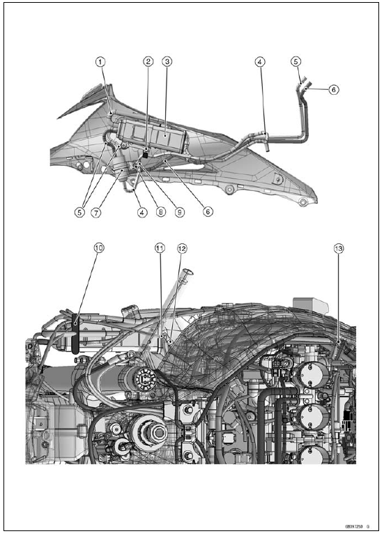
CAL and SEA-B1 Models
1. Run the red hose (return) to outside of the white hose (vacuum).
2. Blue Hose (Breather)
3. Main Harness
4. Clutch Cable
5. Air Bleeder Hose
6. Coolant Reserve Tank Overflow Hose
7. Green Hose (Purge)
8. Clamp (Hold the white hose.)
9. White Hose (Vacuum)
10. Run the main harness, blue the hose, the red hose, the green hose and the white hose in turn from outside of the vehicle. Run the all hoses between the frame and the heat insulation plate.
Run the main harness above all hoses.
11. Run the blue hose and the red hose to inside of the main harness and the clutch cable.
12. Run the green hose above the engine sub harness and run it under the intake air pressure sensor #1 lead.
13. Run the white hose under the main harness.
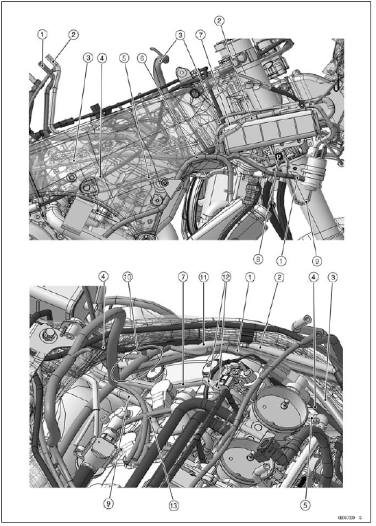
1. Throttle Body Assy
2. White Hose (Vacuum)
3. Green Hose (Purge)
4. Green Tape
5. Clamp (Face the knob forward as shown in the figure.)
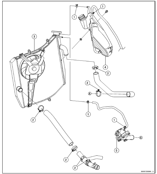
1. Clamps (Face the knob of the clamp as shown in the figure.)
2. Clamp Screws (Face the screw head as shown in the figure.)
3. Radiator
4. Coolant Reserve Tank
5. Thermostat
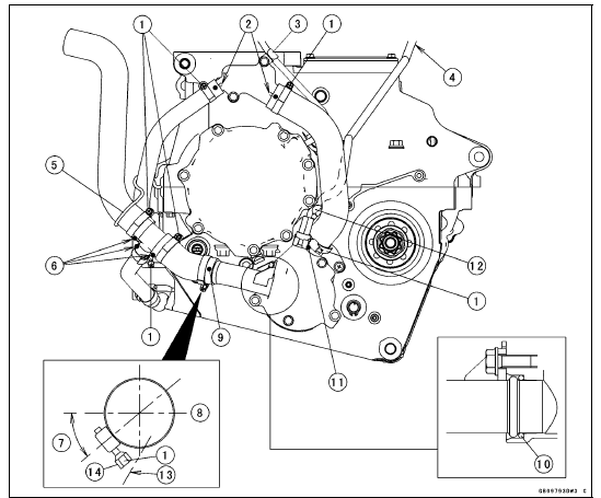
1. Clamp Screws (Face the screw head as shown in the figure.)
2. Align the white marks with the projections of the fitting.
3. Clamp (Hold the alternator lead.)
4. Run the gear position switch lead between the breather hose and the heat insulation rubber plate.
5. Clamp (Hold the water hoses.)
6. Align the white marks with the projections of the water pipe.
7. 0°  40°
40°
8. Outside of Engine
9. Turn the yellow mark to outside of the engine.
10. O-ring
11. Align the yellow mark with the projection of the water pump cover.
12. Clamp (Hold the gear position switch lead.)
13. Extension of Oil Pan Surface
14. Install the clamp so that the screw head is placed inside an extension of the oil pan surface, nearer to the engine.
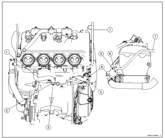
1. Crankcase Breather Hose
2. Clamp (Face the knob of the clamp backward. Do not touch it to the bolt.)
3. Face the yellow mark backward.
4. Clamp Screw (Face the screw head as shown in the figure.)
5. Align the white mark with the line of the thermostat cap.
6. Clamp (Face the knob of the clamp to the top.)
7. Air Bleeder Hose
 KIBS Equipped Models
 Engine No. ZXT00JE003022
Front Fork Installation (Each Fork Leg)
Install the fork so that the top plug end [A] as shown in the
figure.
11 mm (0.43 in.) [B]
Steering Stem Head [C]
Tighten:
Torque - Front Fork Clamp Bolts (Lower): 23 N·m (2.3
kgf·m, 17 ft·lb)
NOTE
Tighten the two lower front fork clamp bolts alternately
two times to ensur ...
Amplifier Input Voltage Inspection
NOTE
Be sure the battery is fully charged.
Turn the ignition switch to OFF.
Remove the upper fairing (see Upper Fairing Removal in
the Frame chapter).
Do not disconnect the connectors.
Connect a digital meter to the amplifier connector [A] with
needle adapter set.
Special To ...
Exploded View
14. Thermostat
15. Frame No. JKAZXT00JJA003074
or JKAZXCJ1
BA003074
G: Apply grease.
HG: Apply high-temperature grease.
L: Apply a non-permanent locking agent.
R: Replacement Parts
S: Follow the specified tightening sequence.
W: Apply water.
1. US, CA and CAL Models
2. Fra ...