
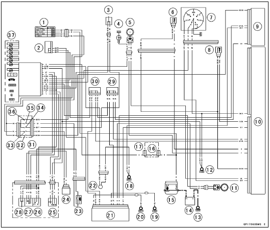
1. Ignition Switch
2. Joint Connector F
3. Stop Watch Button
4. Oil Pressure Switch
5. Crankshaft Sensor
6. Water Temperature Sensor
7. Gear Position Switch
8. Intake Air Temperature Sensor
9. ESD ECU (ZX1000JD/KD)
10. ECU
11. Rear Wheel Rotation Sensor
12. Frame Ground 1
13. Engine Ground
14. Battery 12 V 8.6 Ah
15. Main Fuse 30 A
16. Meter Fuse 10 A
17. Fuse Box 2
18. Frame Ground 3
19. Frame Ground 5
20. Frame Ground 4
21. KIBS Hydraulic Unit
22. Fuel Reserve Switch
23. Headlight Relay
24. Turn Signal Relay
25. Mode Switch
26. Dimmer Switch
27. Turn Signal Switch
28. Passing Button
29. Joint Connector D
30. Joint Connector C
31. Fuse Box 1
32. ESD Fuse 10 A (ZX1000JD/KD)
33. Turn Signal Relay Fuse 10 A
34. Brake Light/Horn Fuse 10 A
35. Headlight Relay Fuse 15 A
36. Ignition Fuse 15 A
37. Meter Unit
 Meter Unit Circuit (ZX1000J Model)
 Immobilizer System (Equipped Models)
Cylinder Compression Measurement
NOTE
Use the battery which is fully charged.
Warm up the engine thoroughly.
Stop the engine.
Remove the spark plugs (see Spark Plug Replacement in
the Periodic Maintenance chapter).
Attach the compression gauge [A] and adapter [B] firmly
into the spark plug hole.
Using the startermo ...
Replacement Parts
Replacement parts must be KAWASAKI genuine or
recommended by KAWASAKI. Gaskets, O-rings, oil seals,
grease seals, circlips, cotter pins or self-locking nuts must
be replaced with new ones whenever disassembled.
Assembly Order
In most cases assembly order is the reverse of disassembly,
howe ...
DFI Servicing Precautions
There are a number of important precautions that should
be followed servicing the DFI system.
This DFI system is designed to be used with a 12 V sealed
battery as its power source. Do not use any other battery
except for a 12 V sealed battery as a power source.
Do not reverse the battery ...