
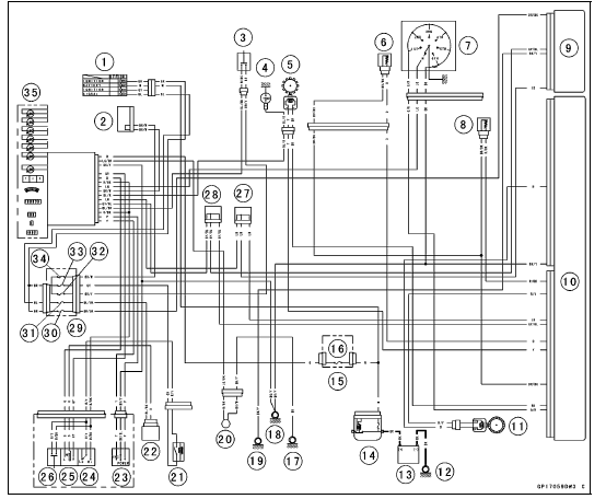
1. Ignition Switch
2. Joint Connector F
3. Stop Watch Button
4. Oil Pressure Switch
5. Crankshaft Sensor
6. Water Temperature Sensor
7. Gear Position Switch
8. Intake Air Temperature Sensor
9. ESD ECU (ZX1000JD/KD)
10. ECU
11. Rear Wheel Rotation Sensor
12. Engine Ground
13. Battery 12 V 6 Ah
14. Main Fuse 30 A
15. Fuse Box 2
16. Meter Fuse 10 A
17. Frame Ground 3
18. Frame Ground 1
19. Frame Ground 4 (ZX1000JD/KD)
20. Fuel Reserve Switch
21. Headlight Relay
22. Turn Signal Relay
23. Mode Switch
24. Dimmer Switch
25. Turn Signal Switch
26. Passing Button
27. Joint Connector D
28. Joint Connector C
29. Fuse Box 1
30. ESD Fuse 10 A (ZX1000JD/KD)
31. Turn Signal Relay Fuse 10 A
32. Brake Light/Horn Fuse 10 A
33. Headlight Relay Fuse 15 A
34. Ignition Fuse 15 A
35. Meter Unit
 Check 3-7 Stop Watch Inspection
 Meter Unit Circuit (ZX1000K Model)
Intake Air Temperature Sensor Output Voltage Inspection
NOTE
Be sure the battery is fully charged.
Turn the ignition switch to OFF.
Remove the fuel tank (see Fuel Tank Removal in the Fuel
System (DFI) chapter).
Disconnect the intake air temperature sensor connector
and connect the measuring adapter [A] between these
connectors as shown in ...
Balance Inspection
Remove the front and rear wheels (see Front/Rear Wheel
Removal).
Support the wheel so that it can be spun freely.
Spin the wheel lightly, and mark [A] the wheel at the top
when the wheel stops.
Repeat this procedure several times. If the wheel stops
of its own accord in various positi ...
Side Stand
The motorcycle is equipped with a
side stand.
A. Side Stand
NOTE
When using the side stand, turn the
handlebar to the left.
Do not sit on the motorcycle while
it is on its side stand or centre stand.
Always kick the stand fully up before
sitting on the motorcycle.
NOTE
The motorcycl ...