
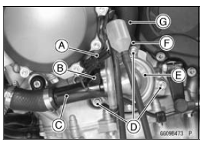
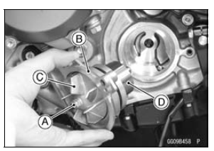
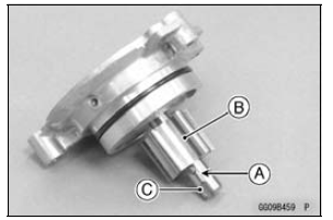
 Oil Pump
 Oil Pump Installation
Air Intake Solenoid Valve Unit Test
Remove the air intake solenoid valve (see Air Intake Solenoid
Valve Removal in the Fuel System (DFI) chapter).
Set the hand tester [A] to the × 1 Ω range and connect it
to the air intake solenoid valve terminals as shown in the
figure.
Special Tool - Hand Tester: 57001-1394
...
Switch Inspection
Using a hand tester, check to see that only the connections
shown in the table have continuity.
Special Tool - Hand Tester: 57001-1394
For the switch housings and the ignition switch, refer to
the tables in the Wiring Diagram.
If the switch has an open or short, repair it or replace it
w ...
For Secondary Fuel Injectors
Remove the fuel tank (see Fuel Tank Removal).
Disconnect the injector connector and connect the harness
adapter [A] between these connectors as shown in
the figure.
Main Harness [B]
Secondary Fuel Injector #1 [C]
Special Tool - Measuring Adapter: 57001-1700
Connect a digital me ...