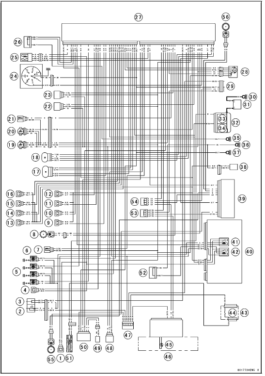


1. Air Intake Solenoid Valve (Other than US, CA and CAL Models)
2. Engine Stop Switch
3. Starter Button
4. Air Switching Valve
5. Stick Coil #1, #2, #3, #4
6. Spark Plugs
7. Intake Air Temperature Sensor
8. Crankshaft Sensor
9. Secondary Fuel Injector #1
10. Secondary Fuel Injector #2
11. Secondary Fuel Injector #3
12. Secondary Fuel Injector #4
13. Primary Fuel Injector #1
14. Primary Fuel Injector #2
15. Primary Fuel Injector #3
16. Primary Fuel Injector #4
17. Idle Speed Control Valve Actuator
18. Subthrottle Valve Actuator
19. Main Throttle Sensor
20. Subthrottle Sensor
21. Water Temperature Sensor
22. Intake Air Pressure Sensor #2
23. Intake Air Pressure Sensor #1
24. Gear Position Switch
25. Oxygen Sensor (Equipped Models)
26. Joint Connector E
27. ECU
28. Exhaust Butterfly Valve Actuator
29. Immobilizer (Equipped Models)/Kawasaki Diagnostic System Connector
30. Engine Ground
31. Battery
32. Starter Relay
33. Main Fuse 30 A
34. ECU Fuse 15 A
35. Frame Ground 2
36. Frame Ground 3
37. Frame Ground 1
38. Fuel Pump
39. KIBS Hydraulic Unit
40. Relay Box
41. Fuel Pump Relay
42. ECU Main Relay
43. Fuse Box 1
44. Ignition Fuse 15 A
45. Oil Pressure/Water Temperature/FI/Immobilizer Warning Indicator Light
46. Meter Unit
47. Joint Connector F
48. Vehicle-down Sensor
49. Immobilizer Antenna (Equipped Models)
50. Immobilizer Amplifier (Equipped Models)
51. Ignition Switch
52. Joint Connector A
53. Joint Connector C
54. Joint Connector D
55. Front Wheel Rotation Sensor
56. Rear Wheel Rotation Sensor
Color Codes:
BK: Black GY: Gray PU: Purple
BL: Blue LB: Light Blue R: Red
BR: Brown LG: Light Green V: Violet
CH: Chocolate O: Orange W: White
DG: Dark Green P: Pink Y: Yellow
G: Green
This page intentionally left blank.
 DFI System Wiring Diagram
 Terminal Numbers of ECU Connectors
Piston Ring End Gap Inspection
Place the piston ring [A] inside the cylinder (upper
crankcase), using the piston to locate the ring squarely
in place. Set it close to the bottom of the cylinder, where
cylinder wear is low.
Measure the gap [B] between the ends of the ring with a
thickness gauge.
Piston Ring End Gap ...
Technical Information-Power Mode
The rider can choose from three engine power modes to suit their preferences
and road conditions.
The FI ECU controls the engine power by adjusting fuel injection, air intake,
and ignition timing. It
enables three-mode selection: Full Power (Mode F), Middle Power (Mode M), and
Low Power (M ...
Seat Cutter Operation Care
1. This valve seat cutter is developed to grind the valve for
repair. Therefore the cutter must not be used for other
purposes than seat repair.
2. Do not drop or shock the valve seat cutter, or the diamond
particles may fall off.
3. Do not fail to apply engine oil to the valve seat cutter
...