Kawasaki Ninja Owners Manual: Clock
To adjust hours and minutes, do the
followings while the motorcycle is at a
stop.
- Turn the ignition switch to “ON”.
- Display the odometer in the multifunction
display. Refer to the “Multifunction
Display” item in this section.
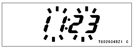
- Push the lower button for more than
2 seconds. Both the hour and minute
displays start blinking.

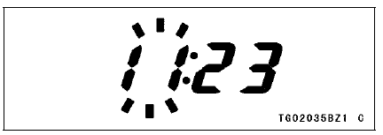
- Push the lower button. The hour display
only blinks. Push the upper button
to advance the hours.

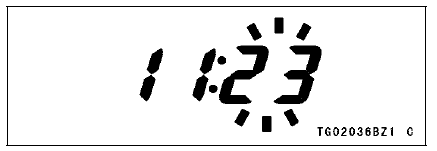
- Push the lower button. The hour display
stops blinking and the minute
display starts blinking. Push the upper
button to advance the minutes.

- Push the lower button. Both the hour
and minute displays start blinking
again.
- Push the upper button. The displays
stop blinking and the clock starts
working.
NOTE
- Pushing the upper button momentarily
advances the hour or minute step
by step. Pushing and holding the button
advances the hour or minute continuously.
- The clock works normally by the back
-up power while the ignition switch is
turned “OFF”.
- When the battery is disconnected,
the clock is reset to 1:00 and starts
working again when the battery is
connected.
This mode gives priority to reading
the gear position rather than the
speedometer reading.
The gear position indicator can
be displayed at the position of the
speedometer on the normal mode.
A ...
When the operator is driving the motorcycle
for optimum fuel-efficiency, the
economical riding indicator appears on
the multifunction meter to indicate favorable
fuel consumption. Monitoring
the ...
Other materials:
Cam Wear Inspection
Remove the camshafts (see Camshaft Removal).
Measure the height [A] of each cam with a micrometer.
If the cams are worn down past the service limit, replace
the camshaft.
Cam Height
Standard:
Exhaust 35.043 35.157 mm
(1.3796 1.3841 in.)
Intake 38.243 38.357 mm
(1.5056 1.5101 in. ...
Connecting Rod Big End
Bearing Insert/Crankpin Wear Inspection
Remove the connecting rod big end (see Connecting Rod
Removal).
Cut strips of plastigage to crankpin width. Place a strip
on the crankpin parallel to the crankshaft installed in the
correct position.
Tighten the connecting rod big end nuts to the specified
torque (see Connecting Rod I ...
Rebound Damping Force Adjustment
The rebound damping force adjuster
is located at the upper end of the rear
shock absorber.
A. Rebound Damping Force Adjuster
B. To increase damping force
C. To decrease damping force
Using a screwdriver turn the rebound
damping force adjuster clockwise
to increase rebound damping or ...


 Race Mode Display
 Economical Riding Indicator