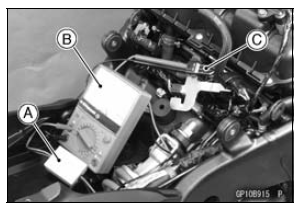

NOTE

Special Tools - Hand Tester: 57001-1394 Peak Voltage Adapter: 57001-1415 Type: KEK-54-9-B
Connections: Crankshaft Sensor Lead Connector Peak Voltage Adapter Hand Tester Y lead ← R lead → (+) BK lead ← BK lead → (–)
Crankshaft Sensor Peak Voltage Standard: 1.9 V or more
If the reading is less than the standard, inspect the crankshaft sensor (see Crankshaft Sensor Inspection).
 Crankshaft Sensor Inspection
 Timing Rotor Removal
Special Tools and Sealant
Compression Gauge, 20 kgf/cm²:
57001-221
Valve Spring Compressor Assembly:
57001-241
Valve Spring Compressor Adapter,
25:
57001-1019
Valve Seat Cutter, 45° - 27.5:
57001-1114
Valve Seat Cutter, 45° - 32:
57001-1115
Valve Seat Cutter, 32° - 28:
57001-1119
Valve Seat Cutter ...
Throttle Body Assy Holder Installation
Be sure to install the new O-rings [A].
Using a high flash-point solvent, clean off any oil or dirt
that may be on the silicone sealant coating area. Dry
them with a clean cloth.
Apply silicone sealant to any two positions of the new O
-ring.
Sealant - Liquid Gasket, TB1211F: 92104-0 ...
Mode-switching
Depress the S-KTRC button on the left handlebar switch
to change the mode. The mode can be changed only when
the throttle grip is closed completely.
The S-KTRC OFF can be selected only when the motorcycle
is at a stop. Changing to mode 1 from S-KTRC OFF
is possible while riding.
NOTE
...