
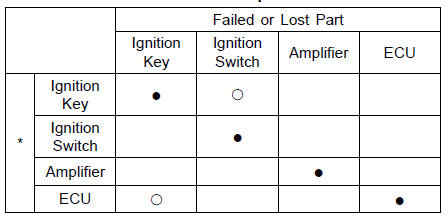
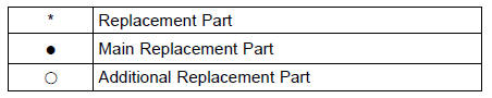
ECU Replacement
Immobilizer Relational Parts Replacement Chart
Immobilizer System Inspection
Immobilizer System Circuit
1. Ignition Switch
2. ECU
3. Immobilizer/Kawasaki Diagnostic System Connector
4. Engine Ground
5. Battery
6. Main Fuse 30 A
7. Frame Ground 1
8. Joint Connector D
9. Joint Connector C
10. Fuse Box 1
11. Ignition Fuse 15 A
12. Meter Unit
13. Joint Connector F
14. Immobilizer Antenna
15. Immobilizer Amplifier
 Ignition Switch Replacement
 Switches and Sensors
Upper Fairing Assembly Disassembly
Remove:
Upper Fairing Assembly (see Upper Fairing Assembly
Removal)
Headlight (see Headlight Removal/Installation in the
Electrical System chapter)
City Light (LED) (see City Light (LED) Removal/Installation
in the Electrical System chapter)
Remove the screws [A], and separate each ...
KIBS Troubleshooting Outline
When an abnormality in the system occurs, the ABS indicator
light (LED) and KIBS indicator light (LED) light up and
the KIBS warning symbol are displayed on the LCD (Liquid
Crystal Display) to alert the rider. In addition, the nature of
the fault is stored in the memory of the KIBS hydraulic uni ...
Throttle Body Assy Holder Installation
Be sure to install the new O-rings [A].
Using a high flash-point solvent, clean off any oil or dirt
that may be on the silicone sealant coating area. Dry
them with a clean cloth.
Apply silicone sealant to any two positions of the new O
-ring.
Sealant - Liquid Gasket, TB1211F: 92104-0 ...