
When an abnormality in the system occurs, the ABS indicator light (LED) and KIBS indicator light (LED) light up and the KIBS warning symbol are displayed on the LCD (Liquid Crystal Display) to alert the rider. In addition, the nature of the fault is stored in the memory of the KIBS hydraulic unit and FI ECU, and when in the self-diagnosis mode, the service code [A] is displayed on the LCD by the “b� and the number of two digits. When repair has been done, the both warning indicator lights (LED) and KIBS warning symbol go off and service codes are not displayed. But the service codes stored in memory of the KIBS hydraulic unit ECU and FI ECU are not erased to preserve the problem history.
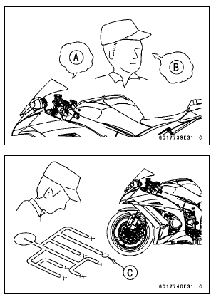
When, due to a malfunction, the ABS and KIBS indicator lights (LED) remain lit, get a thorough understanding of the background before starting the repair work. Ask the rider about the conditions [B] under which the problem occurred and try to determine the cause [C]. Do not rely solely on the KIBS and DFI self-diagnosis function, use common sense; check the brakes for proper braking power, and brake fluid level, search for leaks, etc.
Even when the KIBS and DFI are operating normally, the ABS indicator light (LED) and KIBS indicator light (LED) may light up and the KIBS warning symbol are displayed on the LCD under the conditions listed below. Turn the ignition switch to OFF to go off the indicator light and the KIBS warning symbol.
Much of the KIBS troubleshooting work consists of confirming continuity of the wiring. The KIBS parts are assembled and adjusted by the manufacturer, so there is no need to disassemble or repair them. Replace the KIBS hydraulic unit.
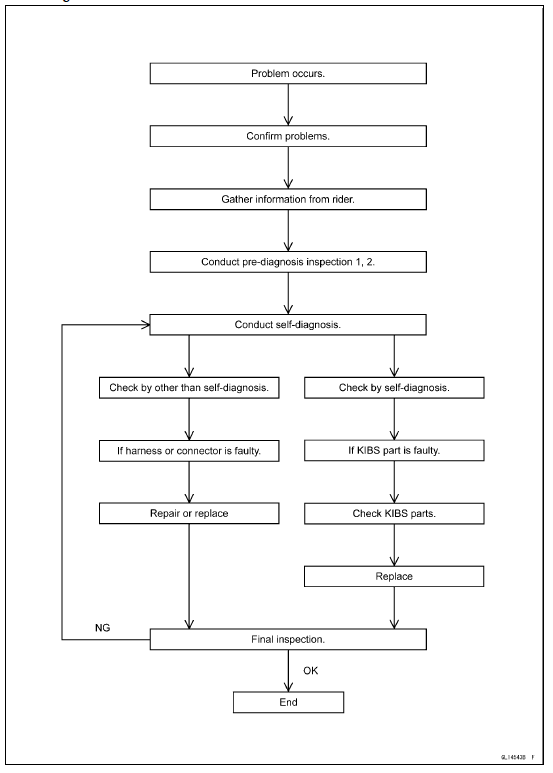
The basic troubleshooting procedures are listed below.
Special Tool - Hand Tester: 57001-1394
If any wiring is poor, replace the damaged wiring.
If the connector is corroded or dirty, clean it carefully. If it is damaged, replace it.
Use the wiring diagram to find the ends of the lead which is suspected of being a problem.
Connect the hand tester between the ends of the leads.
Special Tool - Hand Tester: 57001-1394
Set the tester to the × 1 Ω range, and read the tester.
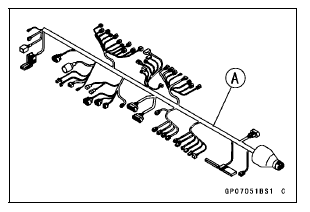
If the tester does not read 0 Ω, the lead is defective. Replace the main harness [A] if necessary.
If no abnormality is found in the wiring or connectors, the KIBS parts are the next likely suspects. Check each part one by one.
If an abnormality is found, replace the affected KIBS part.
KIBS Diagnosis Flow Chart
 KIBS Servicing Precautions
 Inquiries to Rider
Idle Speed
The idle speed inspection should be
performed in accordance with the Periodic
Maintenance Chart.
This motorcycle is equipped with the
Idle Speed Control valve. If the idle
speed is disturbed, inspection of the
idle speed control should be done by
an authorized Kawasaki dealer.
NOTE
While ...
Exhaust Butterfly Valve Actuator Inspection
NOTE
Be sure the battery is fully charged
Remove the front seat (see Front Seat Removal in the
Frame chapter).
Turn the ignition switch to ON.
In the left side view of the motorcycle, check to see
the pulley [A] clockwise [B] and counterclockwise [C]
smoothly.
The pulley turns ...
KIBS Equipped Models
1. Clutch Cable
2. Vacuum Hose (Equipped Models)
3. Left Switch Housing Lead
4. Main Harness
5. Front Brake Hose
6. Throttle Cables
7. Right Switch Housing Lead
8. Bracket (Hold the brake pipes.)
9. Run the meter lead to outside of the meter bracket.
10. Run the vacuum hoses to inside o ...