
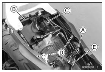
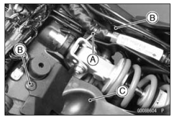
 Flap and Rear Fender Rear Installation
 Rear Fender Front Installation
Meter Operation Inspection
Check 1-1: Switching Inspection
Turn the ignition switch to ON and check the following.
The all LCD segments [A] appear for 3 seconds.
The warning indicator light (Red LED) [B] goes on for 3
seconds and then goes off in a moment after that goes
off.
The warning indicator light (Yellow LED ...
ECU Communication Error (Service Code 39)
ECU Communication Line Inspection
When the data is not sent from the ECU to the meter unit
for more than about 10 seconds, the service code 39 is
displayed.
The data is sent through the CAN communication line.
The service code 39 is detected with the meter unit.
When the user mode, this commun ...
Clutch Cover Assembly
Replace the needle bearings and oil seal with new ones.
NOTE
Install the needle bearings so that the manufacture’s
mark face out.
Install the needle bearings [A] and oil seal [B] position as
shown in the figure.
Press the upper and lower bearings so that the bearing
surface [ ...