
If the tester does not read as specified, replace the relay box.
Relay Circuit Inspection (with the battery disconnected)
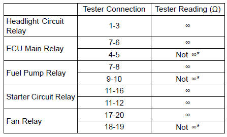
*: The actual reading varies with the hand tester used.
Relay Circuit Inspection (with the battery connected)
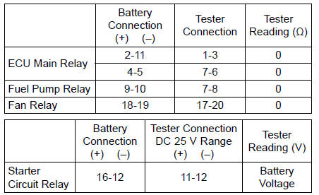
(+): Apply positive lead.
(–): Apply negative lead.
 Relay Box Removal
 Diode Circuit Inspection
Lubrication
Lubrication is necessary after riding
through rain or on wet roads, or any
time that the chain appears dry.
Use a lubricant for sealed chains to
prevent deterioration of chain seals. If
the chain is especially dirty, clean it
using a cleaner for sealed chains following
the instructions suppli ...
Warning Indicator Light (Red)
This red warning indicator light and
the oil pressure warning symbol ( )
should go on whenever the ignition
switch is turned to “ON� and go off after
starting the engine.
A. Warning Indicator Light (Red)
B. Warning Symbols
This red warning indicator light has
the two warning function ...
Cleaning Vehicle before Disassembly
Clean the vehicle thoroughly before disassembly. Dirt or
other foreign materials entering into sealed areas during vehicle
disassembly can cause excessive wear and decrease
performance of the vehicle.
Arrangement and Cleaning of Removed Parts
Disassembled parts are easy to confuse. Arrange ...