
NOTE
Be sure the battery is fully charged.
Do not remove the spark plugs.

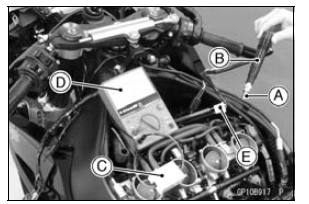
Install the new spark plug [A] into each stick coil [B], and ground them onto the engine.
Connect the peak voltage adapter [C] into the hand tester [D] which is set to the DC 250 V range.
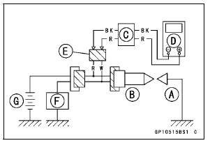
Connect the adapter to the lead wire-peak voltage adapter [E] which is connected between the stick coil connector and stick coil.
ECU [F] Battery [G]
Special Tools - Hand Tester: 57001-1394 Peak Voltage Adapter: 57001-1415 Type: KEK-54-9-B Lead Wire-Peak Voltage Adapter: 57001 -1449

Connections: Adapter (R, +) → Lead Wire-Peak Voltage Adapter (W) Adapter (BK, –) → Lead Wire-Peak Voltage Adapter (R)
| WARNING To avoid extremely high voltage shocks, do not touch the spark plugs or tester connections. |
Stick Coil Primary Peak Voltage Standard: 100 V or more
If the reading is less than the specified value, check the following.
Stick Coils (see Stick Coil Inspection) Crankshaft Sensor (see Crankshaft Sensor Inspection) ECU (see ECU Power Supply Inspection in the Fuel System (DFI) chapter)
Spark Plug Removal
Refer to the Spark Plug Replacement in the Periodic Maintenance chapter.
Spark Plug Installation
Refer to the Spark Plug Replacement in the Periodic Maintenance chapter.
 Stick Coil Inspection
 Spark Plug Condition Inspection
Radiator Fan Relay Inspection
Refer to the Relay Circuit Inspection in the Electrical System
chapter
If the radiator fan relay is normal, check the wiring for
continuity, using the wiring diagram in this section.
Special Tool - Hand Tester: 57001-1394
If the wiring is good, check the ECU for its ground and
power supp ...
Swingarm Removal
Remove:
Rear Wheel (see Rear Wheel Removal in the
Wheels/Tires chapter)
Mud Guard with Rear Brake Hose (see Mud Guard Removal
in the Frame chapter)
Rocker Arm (see Rocker Arm Removal)
Remove:
Brake Hose Clamp Bolt [A]
Unscrew the swingarm pivot shaft nut [A].
Usi ...
Water Temperature Sensor Resistance Inspection
Refer to the Water Temperature Sensor Inspection in the
Electrical System chapter.
If the reading is within the standard, but the problem still
exists, replace the ECU (see ECU Removal/Installation in
the Fuel System (DFI) chapter).
Water Temperature Sensor Circuit
1. ECU
2. Water T ...